
G Fin Tubes – Embedded (G-Type) Finned Tube Manufacturer, Supplier & Exporter
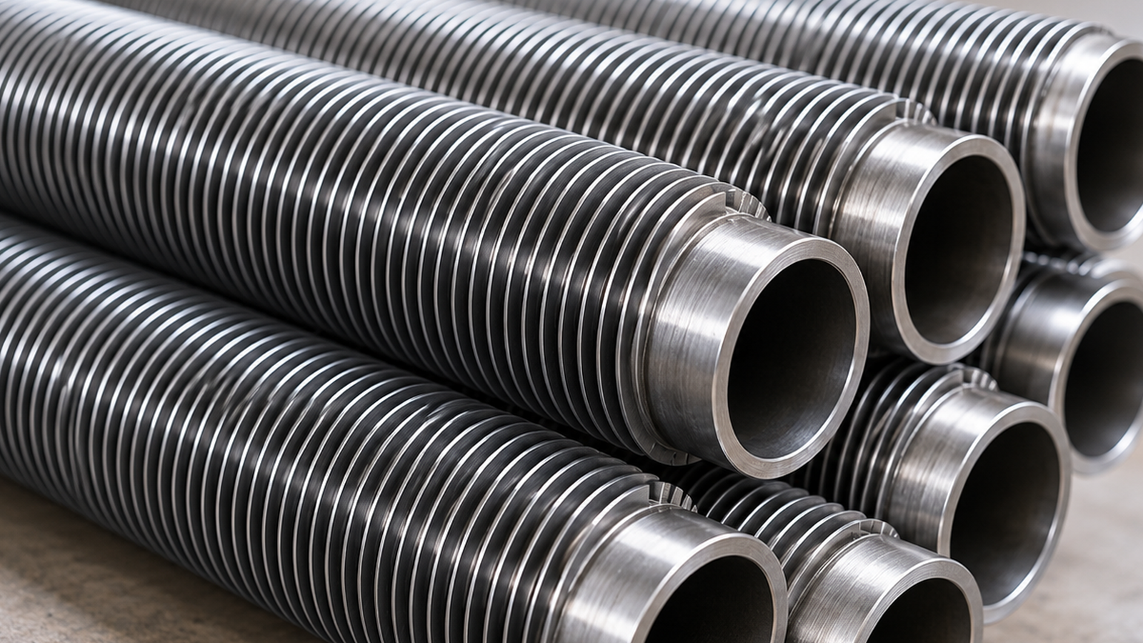
G fin tubes (also called embedded fin tubes, imbedded fin tubes or G-type finned tubes) are heat-exchanger tubes with an aluminium or copper fin strip wound into a helical groove cut in the tube wall and locked in place. The embedded bond keeps the fin tight at tube wall temperatures up to about 400 °C – far higher than wrapped L or KL fins – which makes G fin tubes a standard choice for air-cooled heat exchangers handling hot process streams.
ASC LLP, Mumbai, supplies G fin tubes on carbon steel, stainless steel and copper-alloy base tubes, in straight lengths with bare ends, to API 661 and customer drawings. They are part of our complete range of finned tubes.
Quick specification: base tube 12.7–50.8 mm OD · fin height up to 16 mm · fin thickness 0.3–0.5 mm · 7–11 FPI · aluminium or copper fins · up to approx. 15 m long.
What Is a G Fin Tube?
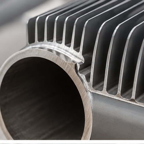
A G fin tube is a type of extended-surface tube in which the fin is embedded into the tube wall rather than wrapped around it or welded to it. A shallow helical groove – the “G” – is machined into the outside of the base tube. A fin strip is then wound edge-on into the groove, and the groove is closed onto the fin root by peening or rolling, so the fin is locked mechanically along its full length.
Because the fin sits inside the tube wall, the bond:
- stays tight through repeated heating and cooling (thermal cycling),
- keeps good metal-to-metal contact for heat transfer at high temperature, and
- resists fin loosening from vibration and handling.
The trade-off is that the groove removes part of the tube wall, and the tube surface between fins is left exposed. That is why G fin tubes are chosen for hot, clean, dry-air service, while extruded fin tubes are preferred in humid or corrosive atmospheres.
How G Fin Tubes Are Made
- Base tube inspection – material certificate, OD and wall checks; wall must allow for the groove depth.
- Grooving – a helical groove, typically a few tenths of a millimetre deep, is cut or ploughed into the tube surface at the required fin pitch.
- Fin winding – an aluminium or copper strip is fed edge-on into the groove and wound under controlled tension; for copper or steel fins the strip is pre-formed first.
- Back-filling (locking) – the groove shoulders are rolled or peened against the fin root, locking the fin into the tube wall.
- Bare-end finishing – fin-free ends are left for tube-sheet joints, and the fin ends are secured.
- Inspection – fin height, pitch and seating checks, fin pull-out tests on samples and hydrostatic testing.
This process gives a continuous, mechanically locked fin along the full tube length.
G Fin Tube Specifications
| Parameter | Details |
| Fin Type | Embedded / imbedded G-type helical fin |
| Base Tube OD | 12.7 mm to 50.8 mm (1/2″ to 2″); 25.4 mm (1″) most common |
| Base Tube Wall | Min. 2.0 mm typical, sized so the wall under the groove meets design pressure |
| Base Tube Materials | Carbon steel (ASTM A179, A214, A106 Gr B), stainless steel (A213 / A249 TP304, TP316, duplex), copper, Cu-Ni |
| Fin Materials | Aluminium (1060, 1100), copper; carbon or stainless steel on request |
| Fin Height | Up to approx. 16 mm (5/8″) |
| Fin Thickness | 0.3 mm to 0.5 mm (0.4 mm typical) |
| Fin Density | 7 to 11 FPI (approx. 276 to 433 fins per metre) |
| Finned OD (on 1″ tube) | 2″, 2.25″, 2.5″ (50.8, 57.15, 63.5 mm) |
| Tube Length | Up to approx. 15 m |
| Bare Ends | As per drawing, for tube sheet / header joints |
| Design Code | API 661 air-cooled heat exchangers, ASME Section VIII |
| Test Certificate | EN 10204 3.1 / 3.2 base tube certificate with finning inspection report |
G Fin Tube Temperature Limits by Fin Material
The maximum operating temperature of a G fin tube depends mainly on the fin material and the fin-to-tube bond:
| Fin Material | Approx. Max Tube Wall Temperature | Typical Use |
| Aluminium | 350 – 400 °C | Refinery and gas-plant air coolers |
| Copper | approx. 350–400 °C (set by fin bond and oxidation) | High heat-transfer coolers, HVAC coils |
| Carbon steel | approx. 450 °C | High-temperature air heaters |
| Stainless steel | approx. 540 °C | Hot, oxidizing service |
Typical industry values for tube wall temperature. Confirm limits with the thermal design and API 661 for your service.
G Fin vs Extruded vs L / KL vs HFW Fin Tubes
Choosing the right fin type is the most important decision for an air cooler or heat-recovery coil. This comparison shows where G fin tubes fit:
| Feature | G Fin (Embedded) | Extruded Fin | L / KL Fin (Wrapped) | HFW Spiral Fin |
| Fin bond | Mechanical, locked in groove | Fin formed from sleeve, very tight | Tension contact (KL knurled) | Welded |
| Max temperature (approx.) | 350–400 °C (Al fin) | 285 °C | 150 °C (L) / 260 °C (KL) | 450 °C+ (steel fin) |
| Corrosion protection of tube | Low – tube exposed between fins | High – tube fully covered | Medium | Low |
| Thermal cycling | Excellent | Good | Poor (L) / fair (KL) | Excellent |
| Effect on tube wall | Groove reduces wall | None | None | None |
| Relative cost | Medium | High | Low | Medium |
| Best for | Hot process streams in clean air | Humid, coastal, corrosive air | Low-temperature HVAC / coolers | Boilers, HRSGs, dirty flue gas |
When to choose G fin tubes
- Process inlet temperature is above the limit of extruded (about 285 °C) or KL (about 260 °C) fins.
- The unit sees frequent start-ups, shutdowns or thermal cycling.
- The site has clean, dry air (inland refineries, gas plants, power stations).
- You want a durable mechanical fin bond at a lower cost than extruded fins.
When to choose another fin type
- Humid, coastal or polluted air – choose extruded fins, or a stainless steel base tube.
- Low temperatures and tight budgets – L or KL fins may be enough.
- Boilers, HRSGs and dusty flue gas – choose HFW spiral or H fin tubes.
G Fin Tube Sizes and Surface Area
The table shows common G fin tube combinations and the approximate outside surface they provide compared with a plain tube:
| Base Tube OD | Finned OD | Fins per Inch | Approx. Outside Surface (m² per m) | Approx. Area Ratio vs Plain Tube |
| 1″ (25.4 mm) | 2.00″ (50.8 mm) | 10 | 1.3 | 16 × |
| 1″ (25.4 mm) | 2.25″ (57.15 mm) | 10 | 1.7 | 22 × |
| 1″ (25.4 mm) | 2.25″ (57.15 mm) | 11 | 1.9 | 24 × |
| 1″ (25.4 mm) | 2.50″ (63.5 mm) | 10 | 2.2 | 28 × |
| 3/4″ (19.05 mm) | 1.75″ (44.45 mm) | 10 | 1.1 | 18 × |
| 1-1/2″ (38.1 mm) | 2.75″ (69.85 mm) | 10 | 2.3 | 19 × |
Surface areas are calculated for 0.4 mm aluminium fins and are approximate; exact values depend on fin thickness and groove geometry.
What to Specify When Ordering G Fin Tubes
Many G fin tube problems come from incomplete specifications. Include these points in your enquiry or purchase order:
- Minimum wall under the groove – the groove reduces wall thickness; state the minimum remaining wall required for your design pressure.
- Base tube specification and grade – e.g. ASTM A179, A214, A213 TP316.
- Tube OD and length, and bare-end lengths at each end for the tube-sheet joint.
- Fin material – aluminium (grade) or copper.
- Finned OD or fin height, fin thickness and fins per inch.
- Fin height and pitch tolerances if tighter than standard practice.
- Testing – hydrostatic test pressure, fin pull-out test frequency, third-party inspection.
- Code requirements – API 661, ASME Section VIII, or project specification.
- Packing – fin protection and crating for export.
G Fin Tube Quality Control & Testing
- Base tube mill test certificate to its material standard (chemistry, mechanical, hydro / NDT)
- Groove depth and remaining wall verification on samples
- Fin pull-out (bond) test on sample lengths
- Fin height, thickness and pitch measurement
- Visual inspection for fin seating, damage and straightness
- Bare-end length and tube length checks
- Hydrostatic test of finished tubes
- Optional third-party inspection (TÜV, BV, SGS, Lloyd’s, DNV) and EN 10204 3.2 certification
Applications of G Fin Tubes
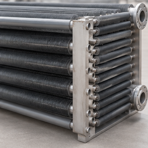
- Air-cooled heat exchangers (fin-fan coolers) in refineries, petrochemical plants and gas processing – especially hot overhead, reactor effluent and product coolers
- Air-cooled condensers for steam and process vapours
- Compressor intercoolers and aftercoolers
- Lube-oil, jacket-water and radiator coolers for engines and gas turbines
- Steam air heaters and process air heaters
- Power-plant and industrial heat recovery heat exchangers
- Chemical, fertilizer and LNG plant coolers
Why Buy G Fin Tubes from ASC LLP?
- Since 1984: decades of supplying heat-exchanger and boiler tubes
- Complete finned tube range: G fin, extruded, L / LL / KL, HFW spiral and H fin tubes from one source
- Certified base tubes: carbon steel, stainless steel and copper alloys with EN 10204 3.1 / 3.2 certificates
- Made to drawing: fin height, density, bare ends and lengths to your air-cooler design
- Inspection welcome: fin pull tests and hydro tests can be witnessed
- Export packing: fin-protecting spacers and seaworthy wooden crates
Related Products
Frequently Asked Questions – G Fin Tubes
What is a G fin tube?
A G fin tube, also called an embedded or imbedded fin tube, is a finned heat-exchanger tube made by cutting a helical groove into the base tube wall, winding an aluminium or copper fin strip into the groove, and closing the groove onto the fin root. The fin is mechanically locked into the tube, giving a strong bond and good heat transfer at higher temperatures.
Why is it called a G fin tube?
The “G” refers to the groove that is machined into the tube wall to hold the fin. G-type fins are sometimes written as “embedded” or “imbedded” fins for the same reason.
What is the maximum temperature of G fin tubes?
With aluminium fins, G fin tubes are commonly rated for tube wall temperatures of about 350–400 °C. Embedded carbon steel fins can go to about 450 °C and stainless steel fins to about 540 °C. This is higher than wrapped L-fin (about 150 °C), KL-fin (about 260 °C) and extruded aluminium fin (about 285 °C) tubes.
What is the difference between G fin and extruded fin tubes?
G fin tubes have fins locked into a groove in the tube wall and handle higher temperatures (about 400 °C with aluminium fins). Extruded fin tubes have fins formed from an aluminium sleeve that fully covers the base tube, giving better corrosion protection but a lower temperature limit (about 285 °C). Choose G fin for hot process streams in clean, dry air; choose extruded for humid, coastal or corrosive atmospheres.
What is the difference between G fin and L fin tubes?
L fin tubes have an L-shaped fin foot wrapped under tension around the outside of the tube, so the bond relies on contact pressure and loosens with heat cycling above about 150 °C. G fin tubes have the fin embedded in a groove, so the bond holds at much higher temperatures and under thermal cycling.
Do G fin tubes need a thicker tube wall?
Yes. The groove removes part of the tube wall, so the base tube must be ordered with enough wall thickness that the remaining wall under the groove still meets the pressure design. Specify the minimum wall thickness under the groove, not only the nominal wall.
What base tube materials can be used for G fin tubes?
Common base tubes are carbon steel (ASTM A179, A214, A106), stainless steel (304, 316, duplex), and copper or copper-nickel. The base tube must be machinable and thick enough for the groove.
Are G fin tubes corrosion resistant?
The fin bond is very durable, but the base tube surface between the fins is exposed to the atmosphere. In humid, marine or polluted air, carbon steel G fin tubes can corrode at the fin root; extruded fin tubes or stainless steel base tubes are better choices there.
What are typical G fin tube sizes?
Base tubes are usually 12.7 to 50.8 mm (1/2″ to 2″) OD, most often 25.4 mm (1″). Fin heights are up to about 16 mm, fin thickness 0.3–0.5 mm and fin density 7–11 fins per inch. A common air-cooler tube is 1″ OD with 2.25″ finned OD at 10 FPI.
Where are G fin tubes used?
G fin tubes are used in air-cooled heat exchangers (fin-fan coolers) for refineries, petrochemical and gas plants, especially for hot process streams; in air-cooled condensers, compressor intercoolers and aftercoolers, lube-oil and jacket-water coolers, steam air heaters and power-plant heat recovery.
How do I test G fin tube fin bond?
Fin bond is checked with a fin pull-out test on sample lengths and by visual and dimensional checks of fin height, pitch and seating in the groove. Finished tubes are also hydrostatically tested, and base tubes carry their own mill test certificates.
What information is needed for a G fin tube quotation?
Base tube material and grade, OD, wall thickness (and minimum wall under groove), tube length, fin material, fin height or finned OD, fin thickness, fins per inch, bare-end lengths, quantity, and any testing, inspection or API 661 requirements.
